
SEPRB Series Right Angle Planetary Gearbox
- Low noise
- High-Capacity Bearing – Increased radial and axial forces
- Spur Gear
- Bevel Gear Rt. Angle
- Backlash ≤13-≤16 arcmin
- 94% efficiency
- Operating Temp -25° to 90°C
- Lifetime lubrication
- Multiple stage configurations
- Customs available
Technical Data
| Product type | 70 | 90 | Reduction ratio | Number of stage | |
| Rated output torque | N.M | 14 | 40 | 3 | 1 |
| 19 | 53 | 4 | |||
| 24 | 67 | 5 | |||
| 18 | 50 | 8 | |||
| 15 | 38 | 10 | |||
| 33 | 97 | 9 | 2 | ||
| 33 | 90 | 12 | |||
| 33 | 82 | 15 | |||
| 33 | 90 | 16 | |||
| 33 | 90 | 20 | |||
| 30 | 82 | 25 | |||
| 33 | 90 | 32 | |||
| 30 | 82 | 40 | |||
| 18 | 50 | 64 | |||
| 15 | 38 | 100 | |||
| Life | Hour | 20,000 | |||
| Instant stop torque | N.M | 66 | 180 | 3 | – |
| 86 | 240 | 4 | |||
| 80 | 220 | 5 | |||
| 80 | 190 | 8 | |||
| 70 | 170 | 10 | |||
| 88 | 260 | 9 | – | ||
| 88 | 240 | 12 | |||
| 88 | 220 | 15 | |||
| 88 | 240 | 16 | |||
| 88 | 240 | 20 | |||
| 80 | 220 | 25 | |||
| 88 | 240 | 32 | |||
| 80 | 220 | 40 | |||
| 80 | 190 | 64 | |||
| 80 | 170 | 100 | |||
| Product type | 70 | 90 | Unit | Number of stage |
| Max radial load | 1650 | 3100 | N | |
| Max axial load | 2100 | 3800 | N | |
| 95 | 1 | |||
| Full load efficiency | 94 | % | 2 | |
| Weight | 2.1~2.2 | 4.8~4.9 | Kg | 1 |
| 2.4~2.6 | 5.5~5.6 | 2 | ||
| Operating temperature | -25 ~ +90 | ℃ | ||
| IP | IP54 | |||
| Lubrication type | Lifetime lubrication | |||
| Mounting type Any | Any | |||
The max radial and axial torque work in the location of the center of output shaft when the out speed is 100RPM.
| Product type | 70 | 90 | Reduction ratio | |
| Moment of inertia | Kgcm2 | 0.218~0.329 | 0.925~1.408 | 3 |
| 4 | ||||
| 5 | ||||
| 8 | ||||
| 10 | ||||
| 0.218~0.326 | 0.907~1.245 | 9 | ||
| 12 | ||||
| 15 | ||||
| 16 | ||||
| 20 | ||||
| 25 | ||||
| 32 | ||||
| 40 | ||||
| 64 |
| Product type | 70 | 90 | Number of stage | |
| Backlash | arcmin | <16 | <13 | 1 |
| <18 | <15 | 2 |
| Product type | 70 | 90 | |||
| Numberof stage | 1 | 2 | 1 | 2 | |
| Torsional stiffness | N.M/arcmin | 2.2 – 4.1 | 3.3-5.3 | 4.7 – 10.8 | 9.0 – 14.1 |
| Noise | dB(A) | 70 | 73 | ||
| Max input speed | min-1 | 13000 | 7000 | ||
| Recommend input speed | min-1 | 4000 | 4000 | ||
1. The moment of inertia is related with input shaft.
2. Noise test standard, distance 1m, measured noload running with an input speed of 3000rpm.
3. The max radial and axial torque work in the location of the center of output shaft when the out speed is 100RPM.
4. The maximum input speed is designed to software.
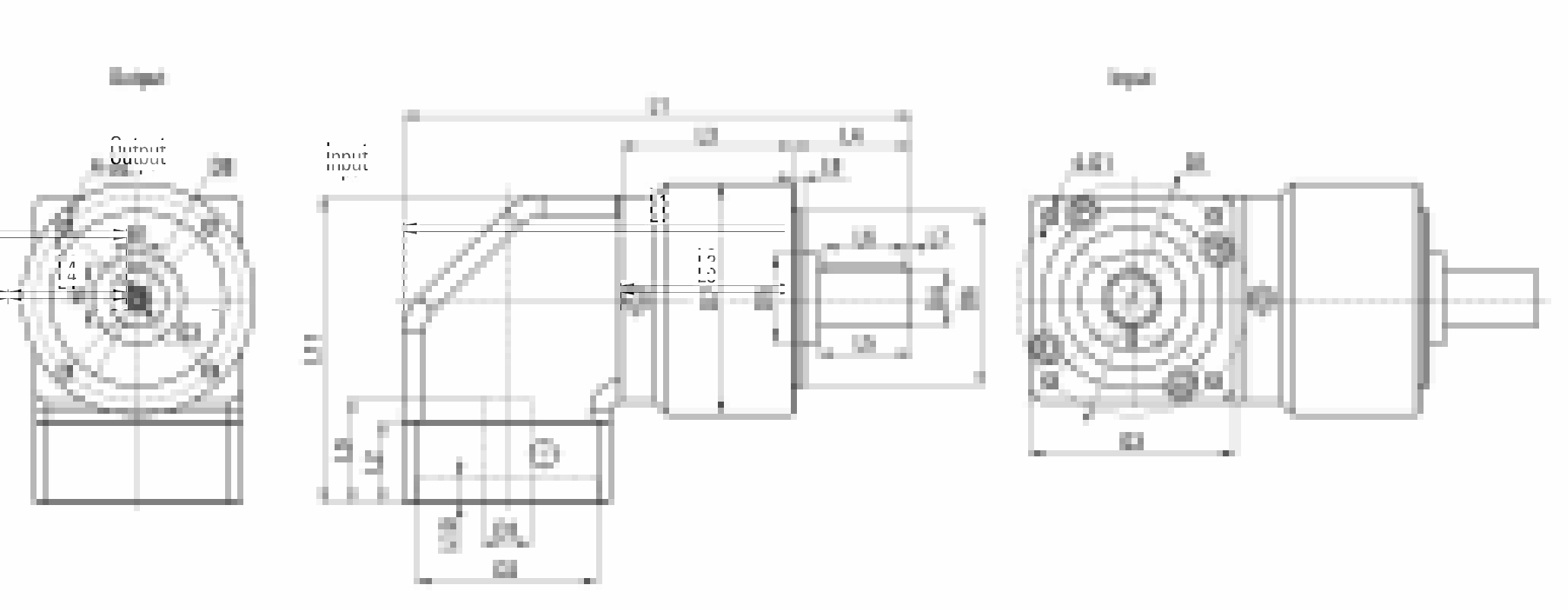
Dimensions
Type and Model Number
60 |
SEP |
10 |
( ) |
(S) |
– |
7 5 0 |
① |
② |
③ |
④ |
⑤ |
⑥ |
| ① | Gear head frame size: 60 |
| ② | Gear head series code: |
| SEP: Inline | |
| SEPR: Right angle | |
| SEPB: Inline Large Output Bearing | |
| SEPRL: Right angle Large Output Bearing | |
| ③ | Gear ratio : |
| Single stage 3,4,5,8,10 | |
| Two stage 9,12,15,16,20,25,32,40,64 | |
| ④ | Input Flange: 1(Round), 2 (Square) |
| ⑤ | Input shaft type |
| S: Over locking (Omission) (Can use it whatever motor shaft has keyway or not) | |
| S: Locking with locking ring (Can use it whatever motor shaft has keyway or not) | |
| ⑥ | S2: Locking with keyway (Input shaft with key) |
| K: With keyway | |
| A: Other type (Please contact with us) | |
| Applicable servo motor power (W) |
| PN | 70SEPRB | 90SEPRB | ||
| Number of stage | 1 | 2 | 1 | 2 |
| L1 overall length | / | / | / | / |
| L3 body length | 51 | 64 | 67 | 84.5 |
| Output | ||||
| L12 overall height | 85.5 | 119.5 | ||
| L4 output shaft length | 36 | 46 | ||
| L5 output length to the shaft shoulder | 28 | 36 | ||
| L6 key length | 25 | 32 | ||
| L7 key length to the shaft end | 2 | 2 | ||
| L8 protruding length | 3 | 4 | ||
| D4 output shaft diameter | Φ16h7 | Φ22h7 | ||
| D5 shaft shoulder diameter | Φ30 | Φ35 | ||
| D6 protruding diameter | Φ52h7 | Φ68h7 | ||
| D7 body diameter | Φ70 | Φ90 | ||
| D8 hole circle | Φ62 | Φ70 | ||
| B1 key width | 5 | 6 | ||
| H1 key height | 18 | 24.5 | ||
| G3 center screw hole | M5X12 | M6X16 | ||
| Input | ||||
| L2 input flange length | For more detailed information, please consult the manufacturer | |||
| L9 motor shaft length | ||||
| L10 protruding depth | ||||
| D1 mounting hole distribution circle | ||||
| D2 protruding diameter | ||||
| D3 input shaft diameter | ||||
| G1 mounting threads hole x depth | ||||
| Q3 input flange | □60 | □80 | ||
※ Input size made according to motor size.
※ The dimensions of L9, L10, D1, D2, D3, Q3, and G1 are installation dimensions for customer’s motor, and the total length of L1 depends on the size of customer’s motor.