
Assembly Instructions
Use these one-stage assembly drawings when mounting SEI SB or SBR planetary gearboxes to servo or stepping motors. For ratio selection, flange adapters, and Economy or AGV series pairing, contact us engineering or request a quote with your motor model and target torque.
Always verify shaft length, keyway, and adapter plate dimensions against your motor drawing before assembly. Torque all fasteners to the values shown on the individual assembly PDF for your frame size.
Assembly Procedure
If a customer personally assembles the servo motor and reducer please use the following guidance. The reducer flange to which the servo motor is attached has different dimensions based on the motor specified. Therefore, assembly may be impossible for some motor. Make sure the correct motor is specified before ordering the reducer.
Motor Assembly (Without Key)
- ① Take off the rubber cap, turn the input shaft, and match the head of the bolt hole of set screw. Make sure that the set bolt is loosened.
- ② Gradually put the motor shaft into the input shaft (Ensure that it is smoothly put in without jam). Be careful not to be inserted with the motor tilted.
- ③ Attach the motor to the reducer and fasten the bolt with designated fastening torque. See Table 1.
- ④ Fasten the set bolt of the input shaft with designated fastening torque wrench, etc. See Table 2.
- ⑤ Put on the rubber cap. It is the end of assembling.
Table 1 – Motor Combination Bolt Fastening Torque
| Bolt Size | Torque (N·m) | Torque (kgf·cm) |
|---|---|---|
| M3 | 1 | 10 |
| M4 | 3 | 30 |
| M5 | 5.8 | 60 |
| M6 | 9.8 | 100 |
| M8 | 19.6 | 200 |
| M10 | 39.2 | 400 |
| M12 | 68.6 | 700 |
| M16 | 168 | 1650 |
Table 2 – Input Shaft Set Bolt Fastening Torque
| Bolt Size | Torque (N·m) | Torque (kgf·cm) |
|---|---|---|
| M3 | 1.5 | 15 |
| M4 | 3.5 | 35 |
| M5 | 7.1 | 71 |
| M6 | 12 | 120 |
| M8 | 30 | 300 |
| M10 | 60 | 612 |
Reducer Assembly
When jointing a reducer with the device, make sure that the combining side is plane without inconsistency, and when assemble reducer onto equipment, ensure assembly surface smooth and without burr. See Table 4.
Table 4 – Reducer Combination Bolt Fastening Torque
| Bolt Size | Torque (N·m) | Torque (kgf·cm) |
|---|---|---|
| M5 | 5.8 | 60 |
| M6 | 9.8 | 100 |
| M8 | 19.6 | 200 |
| M10 | 39.2 | 400 |
| M12 | 68.6 | 700 |
| M16 | 168 | 1650 |
Connection to Output Shaft
Cautions
- •When assemble a coupling, pulley, etc. onto the output shaft, make sure that excessive axial load not be given to the output shaft.
- •In case of strongly hitting the shaft with a hammer, the shaft inlet or the inside of the reducer may be damaged, therefore it shall be prohibited.
- •If the shaft or key of a coupling assembled is loosed, it may cause carbonization, so be careful when assembling.
- •For assembling of a coupling, fix the key with a set bolt.
- •Please adjust shaft centre carefully in connecting.
Gearbox–Motor Matching
- Match gearbox frame size and input adapter to your motor flange and shaft diameter.
- Confirm single-stage vs multi-stage ratio before selecting the assembly drawing.
- Economy Series (SEP/SEPR) and high-precision SB/SBR lines use different adapter kits - specify the series when ordering.
- For AGV/AMR drive systems, see SPG/SAGV/SRS catalogs and the planetary gearbox AGV series pages.
Need help selecting a gearbox for your motor? Request a quote or see the planetary gearbox guide.
SB Series - Servo (1-stage)
5 assembly drawings
 PDF
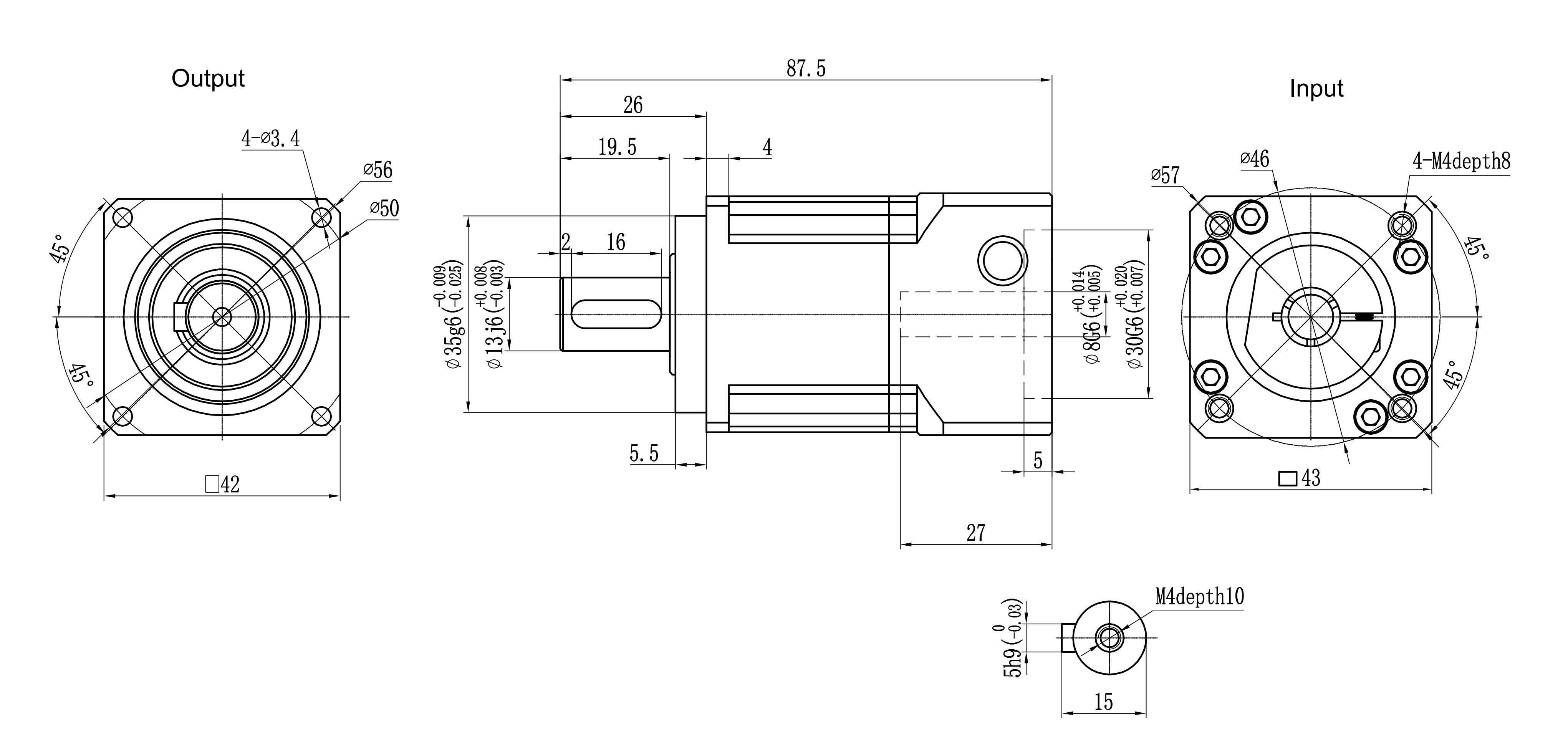
PDFFrame 042 · 1-stage
042SB Servo Motor Assembly
One-stage dimensional drawing for mounting a servo motor to the 042SB planetary gearbox.
Download drawing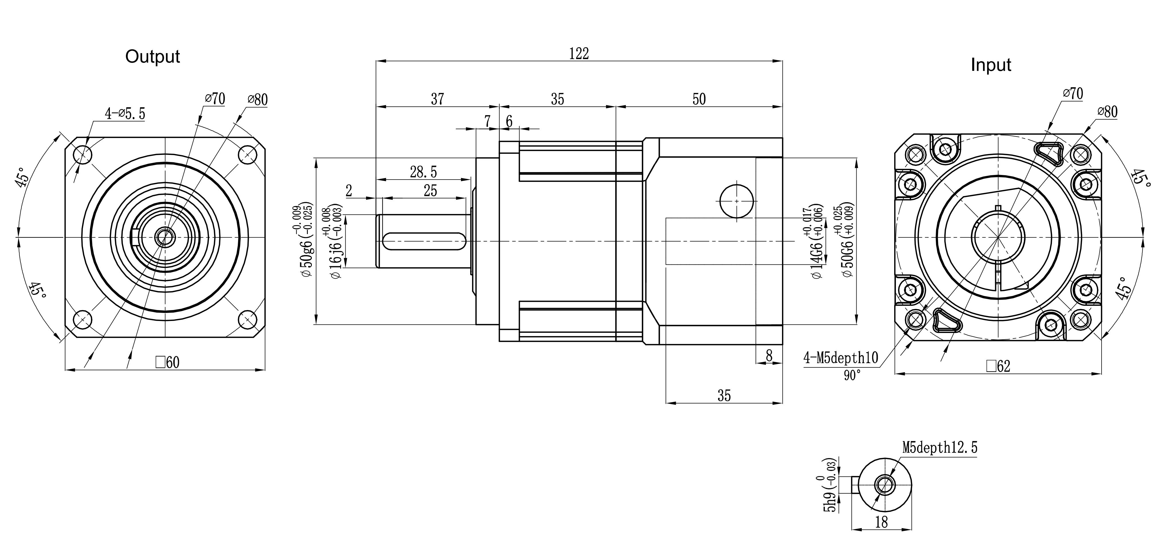 PDF
PDFFrame 060 · 1-stage
060SB Servo Motor Assembly
One-stage dimensional drawing for mounting a servo motor to the 060SB planetary gearbox.
Download drawing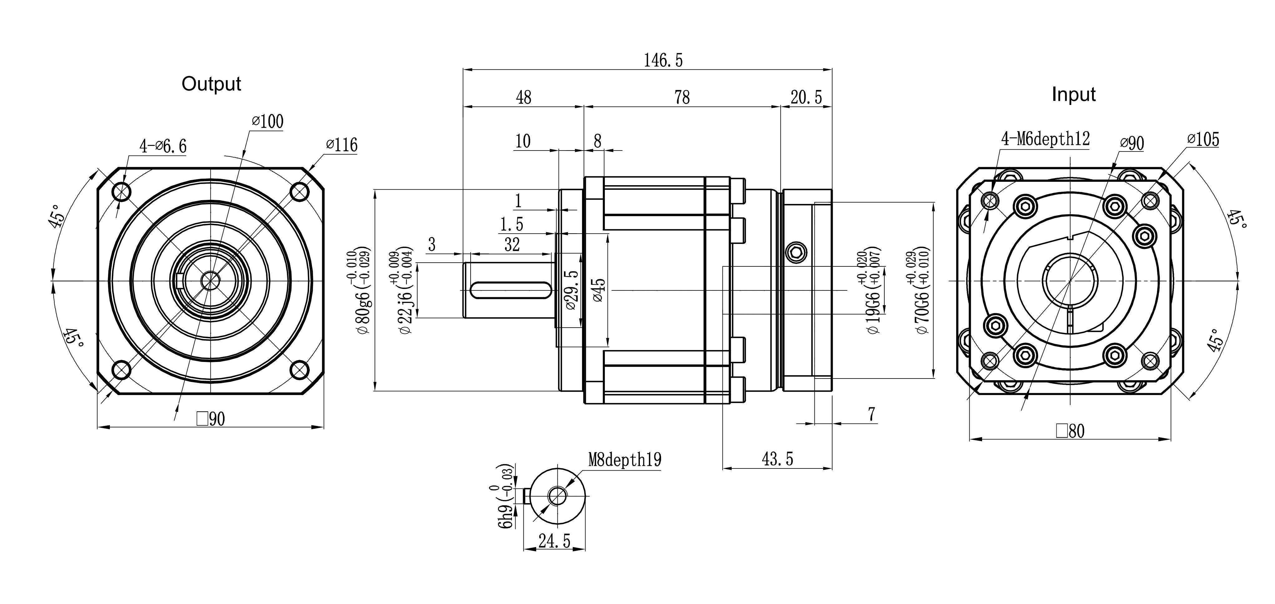 PDF
PDFFrame 090 · 1-stage
090SB Servo Motor Assembly
One-stage dimensional drawing for mounting a servo motor to the 090SB planetary gearbox.
Download drawing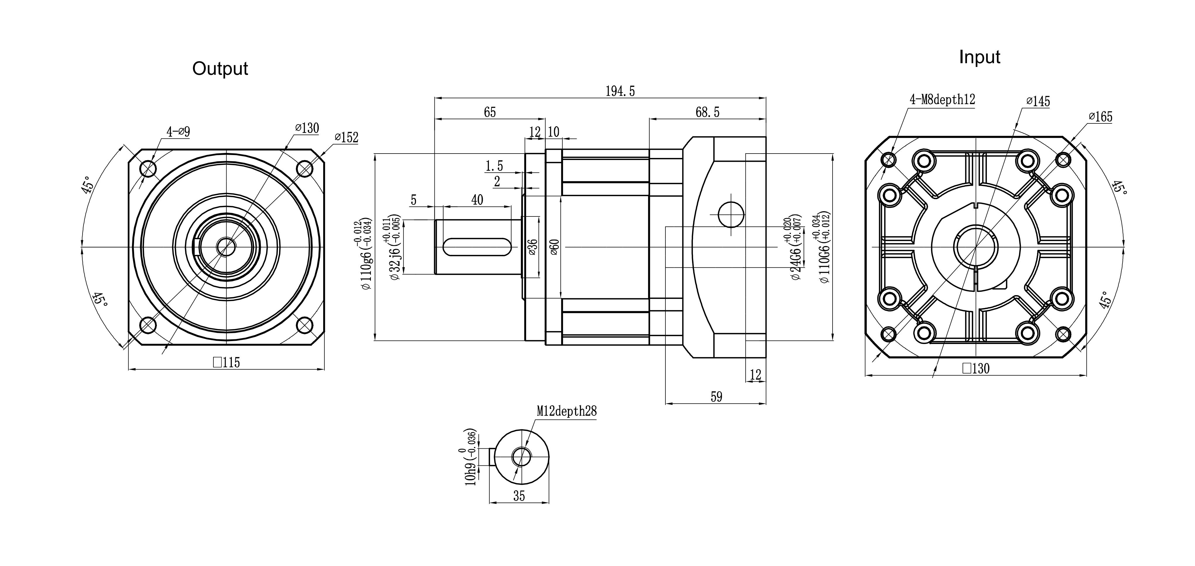 PDF
PDFFrame 115 · 1-stage
115SB Servo Motor Assembly
One-stage dimensional drawing for mounting a servo motor to the 115SB planetary gearbox.
Download drawing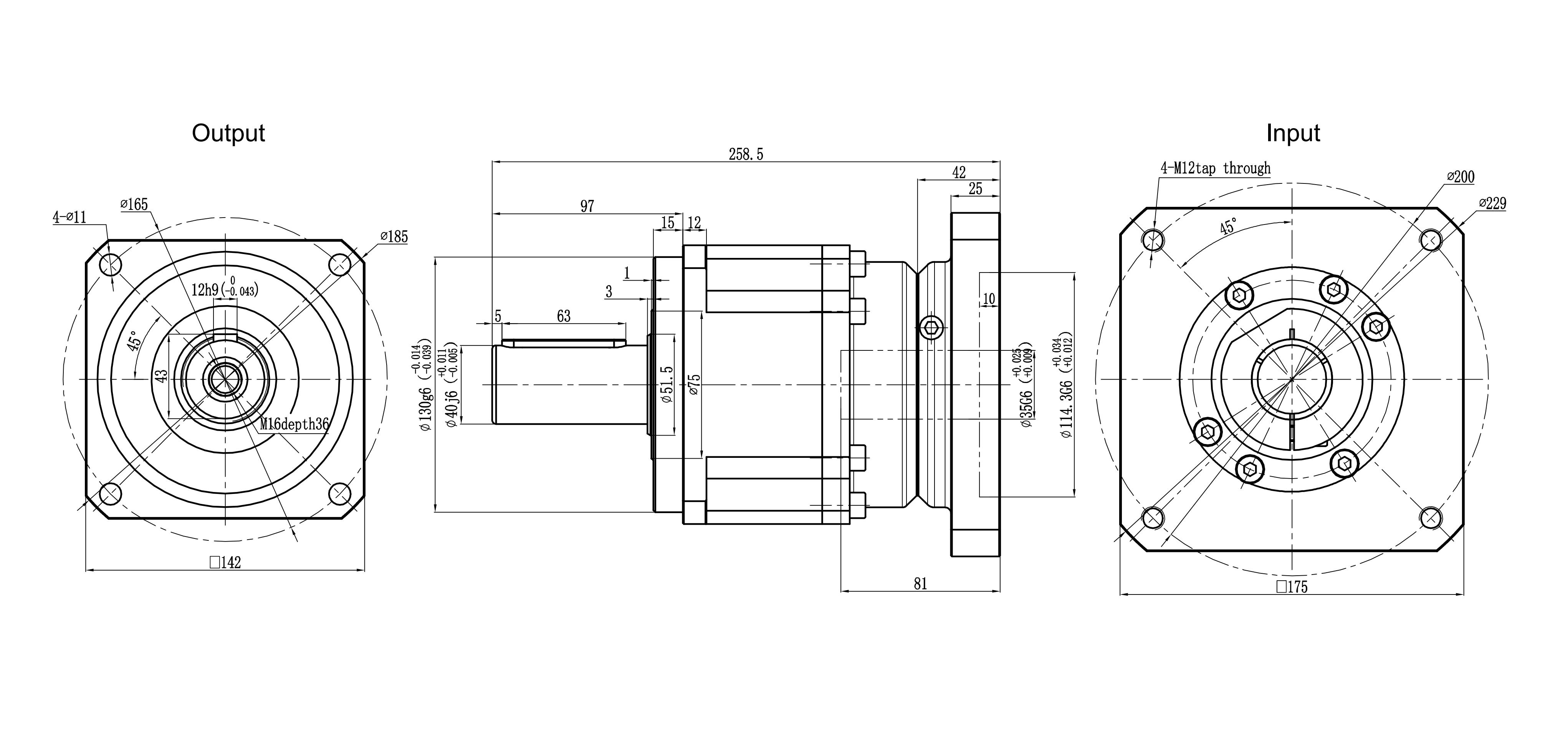 PDF
PDFFrame 142 · 1-stage
142SB Servo Motor Assembly
One-stage dimensional drawing for mounting a servo motor to the 142SB planetary gearbox.
Download drawing
SB Series - Stepper (1-stage)
4 assembly drawings
 PDF
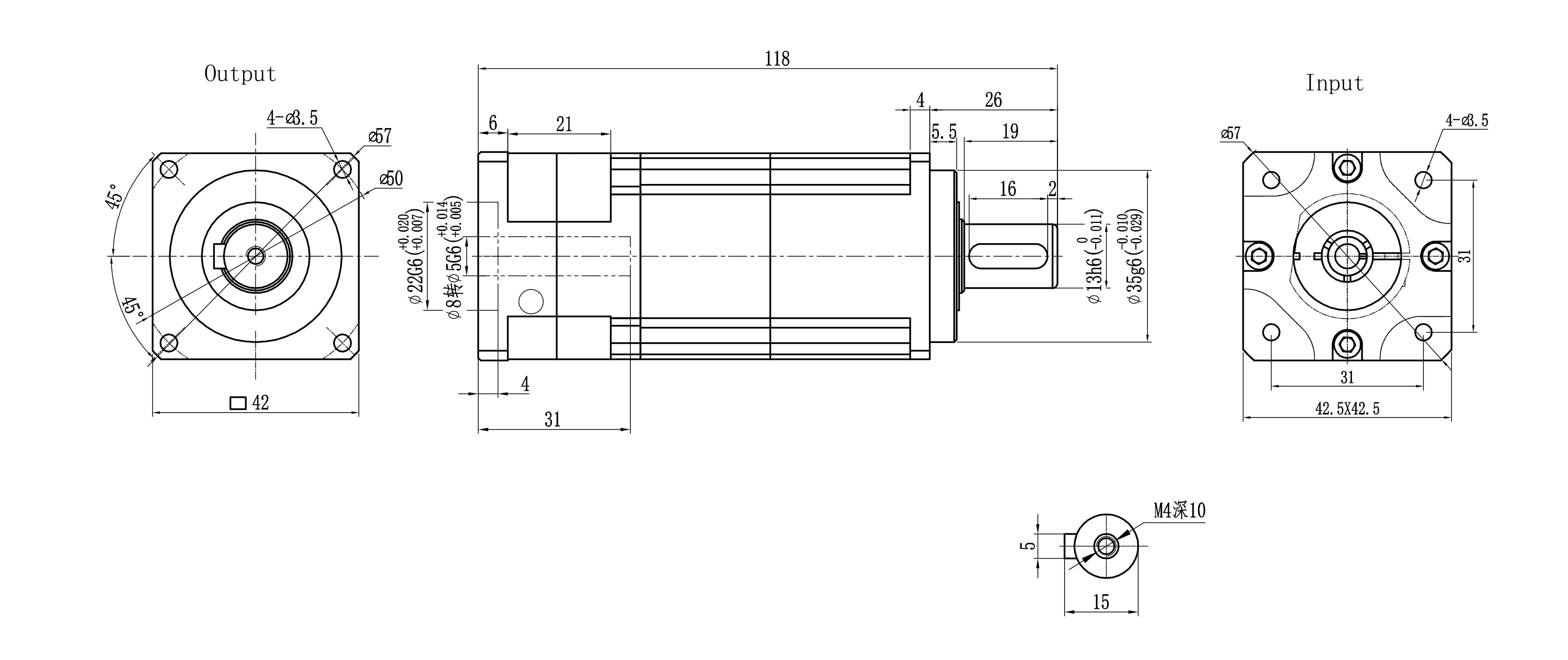
PDFFrame 042 · 1-stage
042SB Stepper Assembly
One-stage dimensional drawing for mounting a stepping motor to the 042SB planetary gearbox.
Download drawing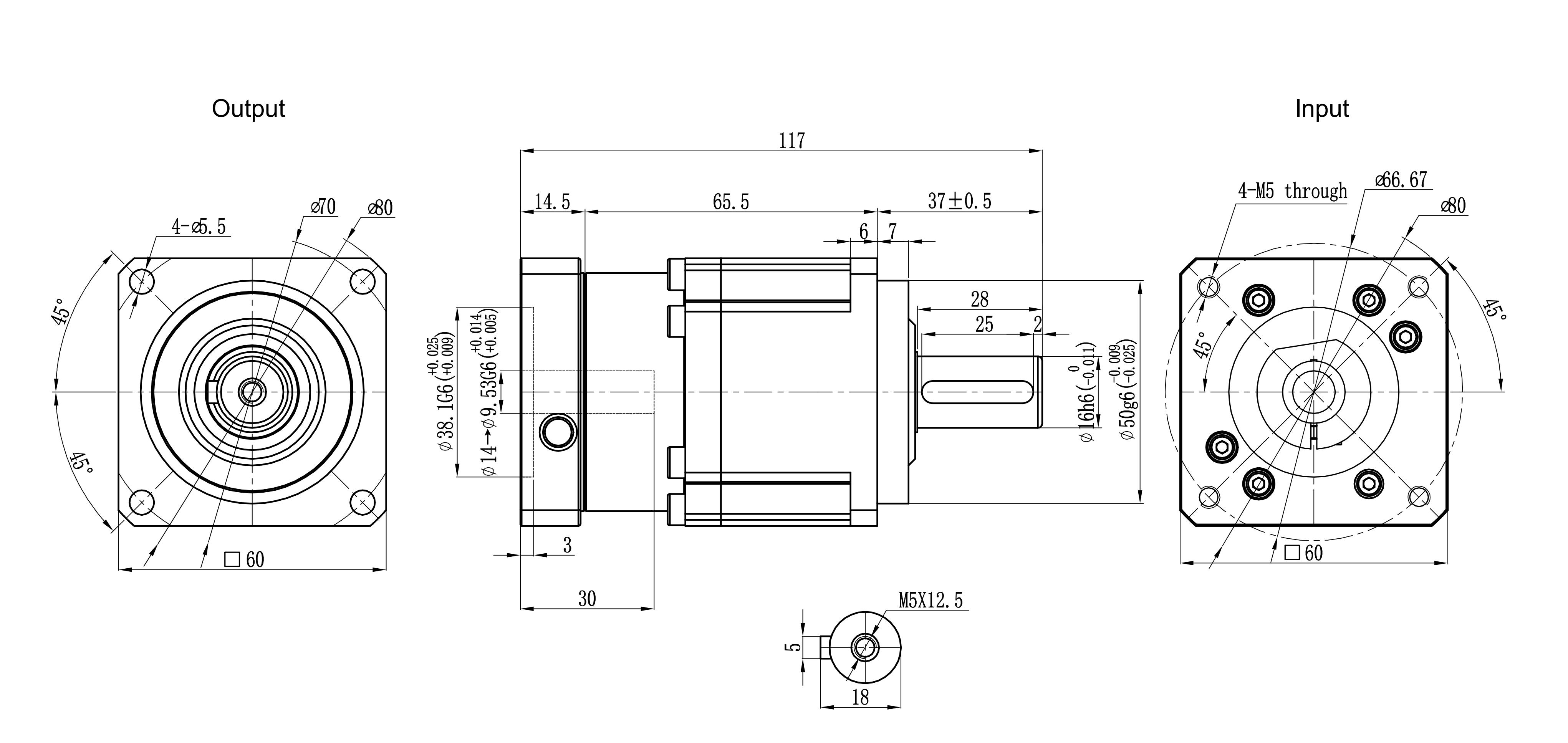 PDF
PDFFrame 060 · 1-stage
060SB Stepper Assembly
One-stage dimensional drawing for mounting a stepping motor to the 060SB planetary gearbox.
Download drawing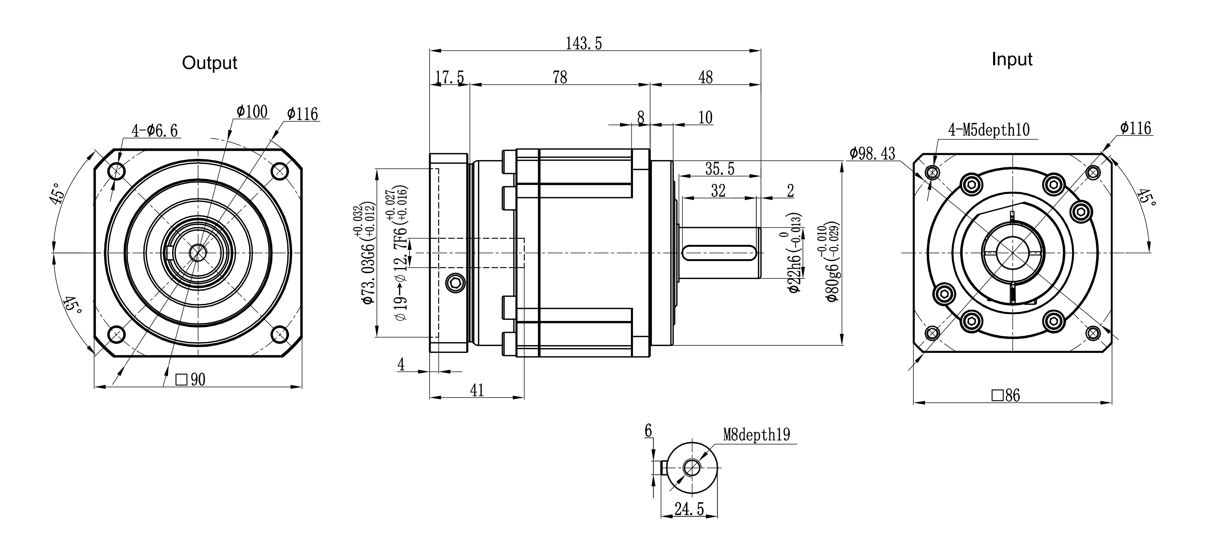 PDF
PDFFrame 090 · 1-stage
090SB Stepper Assembly
One-stage dimensional drawing for mounting a stepping motor to the 090SB planetary gearbox.
Download drawing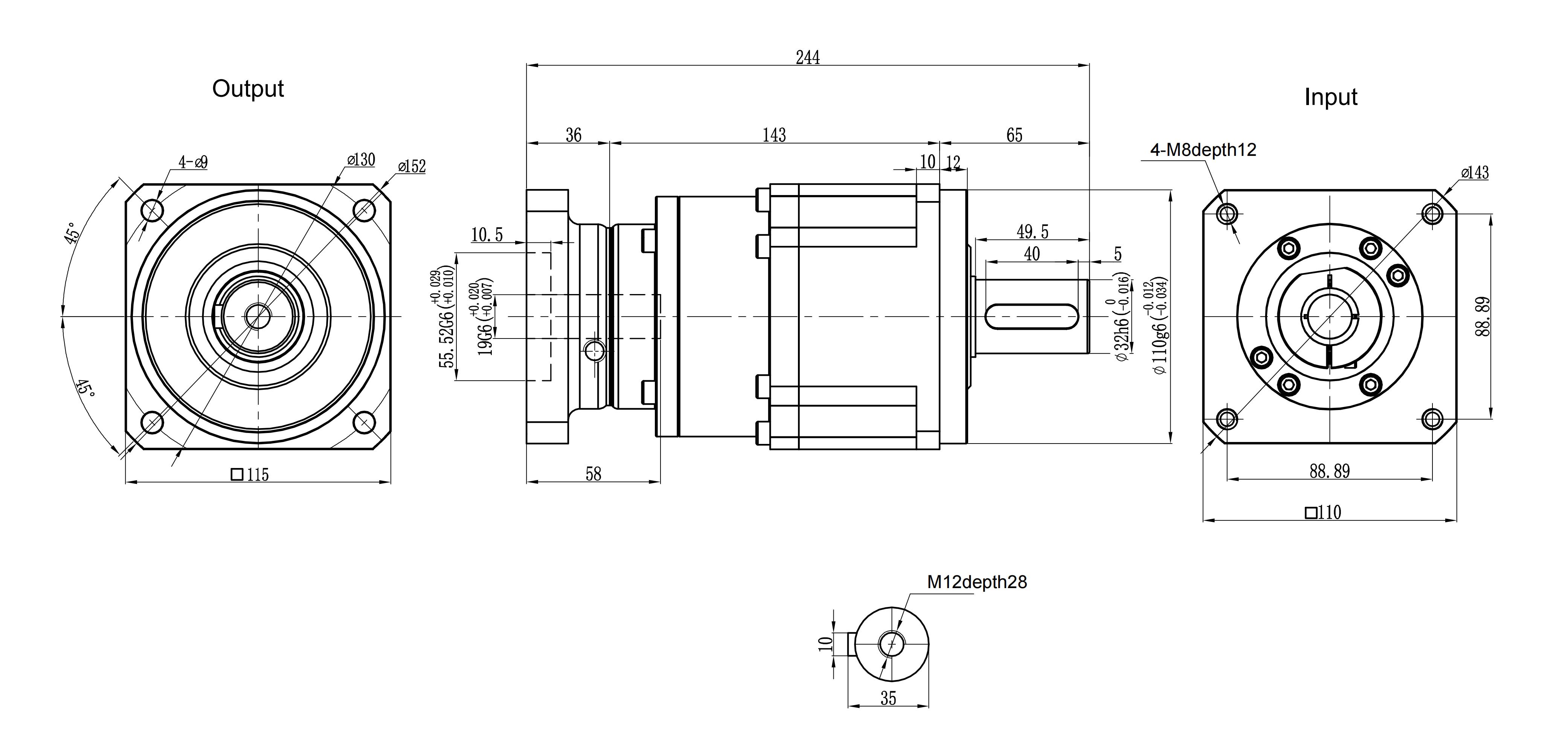 PDF
PDFFrame 115 · 1-stage
115SB Stepper Assembly
One-stage dimensional drawing for mounting a stepping motor to the 115SB planetary gearbox.
Download drawing
SBR Series - Servo (1-stage)
4 assembly drawings
 PDF
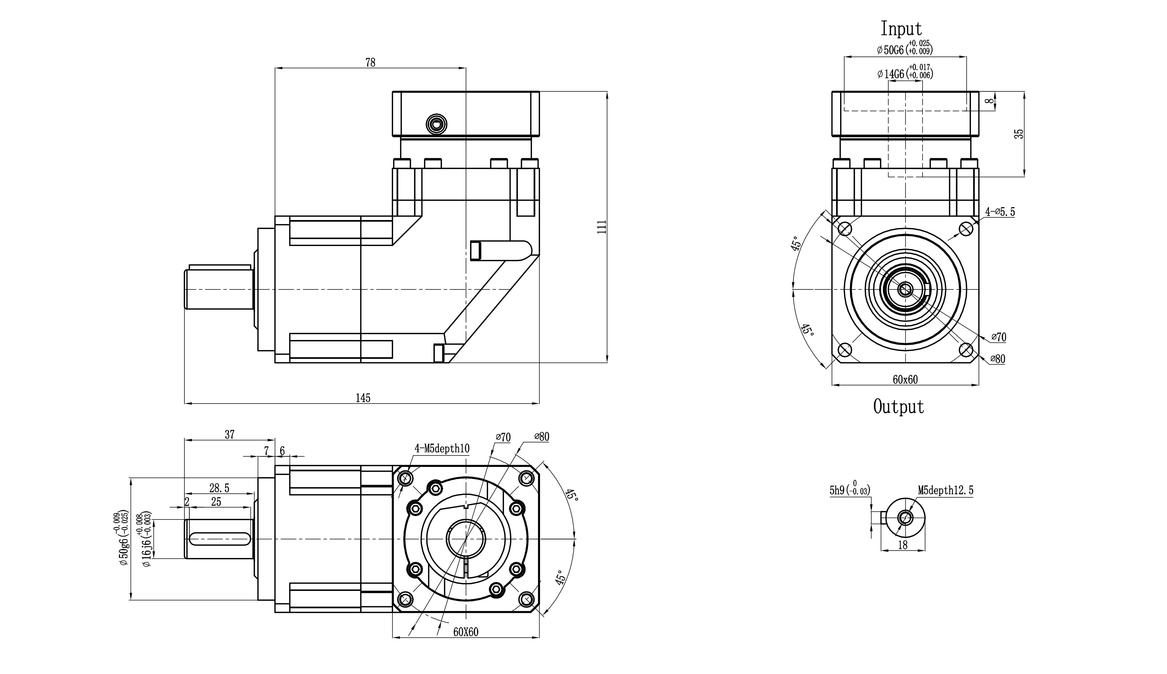
PDFFrame 060 · 1-stage
060SBR Servo Motor Assembly
One-stage dimensional drawing for mounting a servo motor to the 060SBR right-angle planetary gearbox.
Download drawing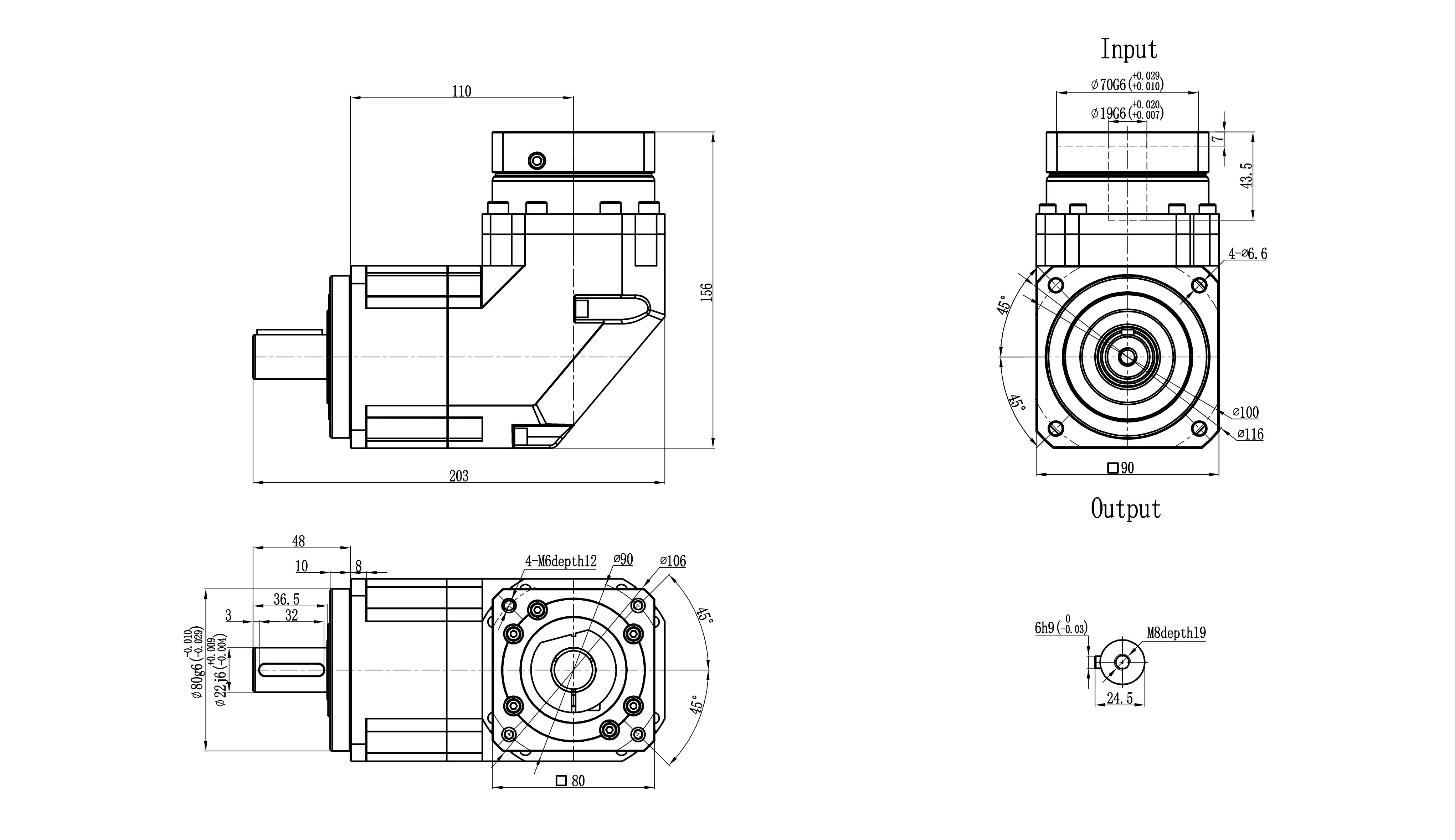 PDF
PDFFrame 090 · 1-stage
090SBR Servo Motor Assembly
One-stage dimensional drawing for mounting a servo motor to the 090SBR right-angle planetary gearbox.
Download drawing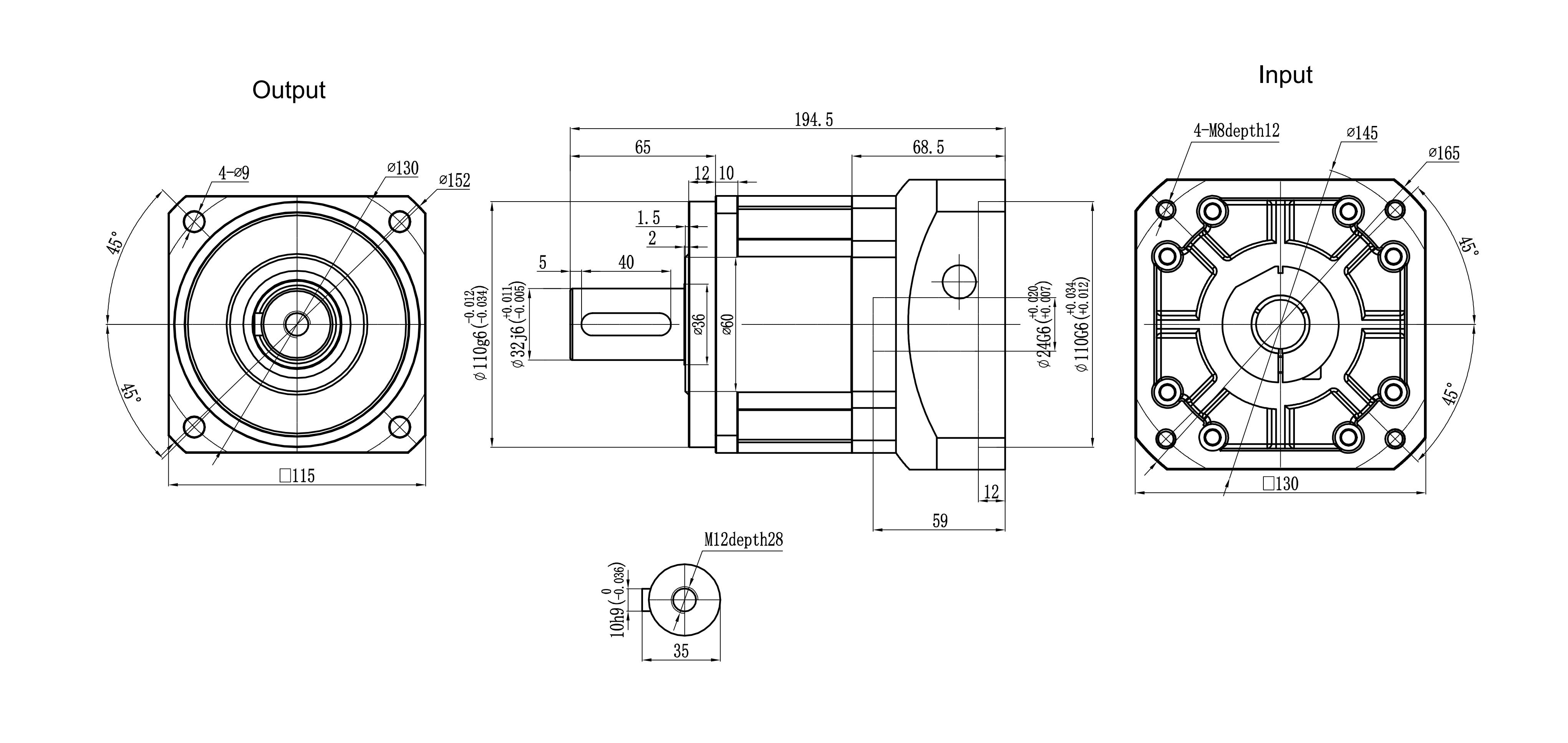 PDF
PDFFrame 115 · 1-stage
115SBR Servo Motor Assembly
One-stage dimensional drawing for mounting a servo motor to the 115SBR right-angle planetary gearbox.
Download drawing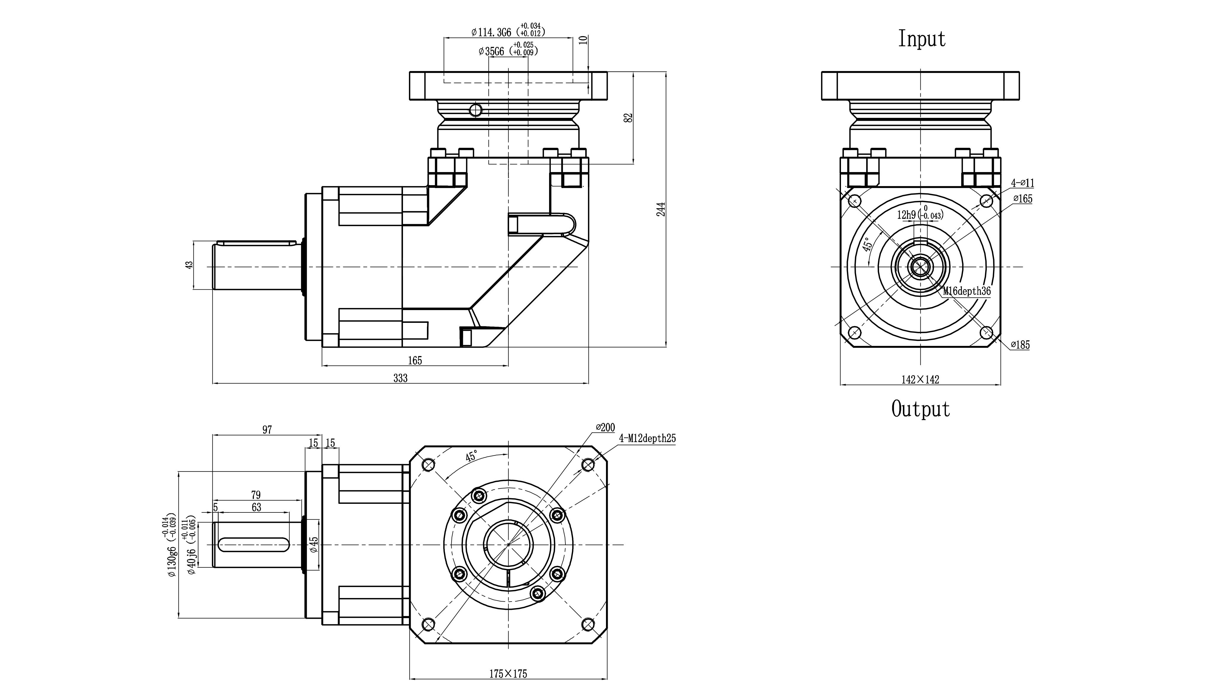 PDF
PDFFrame 142 · 1-stage
142SBR Servo Motor Assembly
One-stage dimensional drawing for mounting a servo motor to the 142SBR right-angle planetary gearbox.
Download drawing